
This post is a continuation of Part 1 on How to Connect a Car Relay. Lately, we have gone through how a relay works and the steps to connecting the car relay.
This part 2 will now look at how to
– plug the 2 positions switch,
– connect a modular electrical relay.
Plugin the 2-position switch
This type of switch’s connection technology requires the use of “Faston” terminals or crimp clip terminals with a width of 6.3 mm.
- Strip the wires.
- Crimp each terminal with a crimping tool.
- Insert the lugs into the corresponding tab.
- Then connect the wires according to the wiring diagram.
- From your fuse box located under your dashboard, find a fuse reserved for accessories.
- Connect a wire to it, which will be the + wire supplying your control circuit via the switch.
- Connect the other end of your wire to the “common” terminal of your switch.
Good to know: the “common” terminal is marked C or L.
On the other terminal of the switch, attach a wire with a lug.
Use this wire to connect to your relay located in the engine compartment.
Good to know: try to find a passage to the engine compartment using a wire bundle’s existing path.
Connect the relay
- Continue the connection, following the wiring diagram, starting with the control part.
- Take the wire connected to the switch that you passed between the passenger compartment and the engine compartment, and connect it to terminal 85 of your relay.
- Connect terminal 86 to the ground using, for example, the fixing screw of your relay (if it is in contact with a metal part of your body).
- Now connect the power part of your relay to power your additional headlights, for example. Note that the power circuit will be supplied via a protective fuse.
- Start from the + battery with a wire to connect a fuse holder.
- From the other terminal of the fuse holder and always with a wire, go to terminal 30 of your relay.
Good to know: this connection feeds the contact of your relay.
- Finally, connect terminal 87 of your relay to the + terminal of your additional headlights.
- And connect the second terminal of the headlights to ground.
Your circuit is now operational.
Case 2: Connect a modular electrical relay
A modular relay is used, for example, to control a siren or a horn.
Get a modular relay
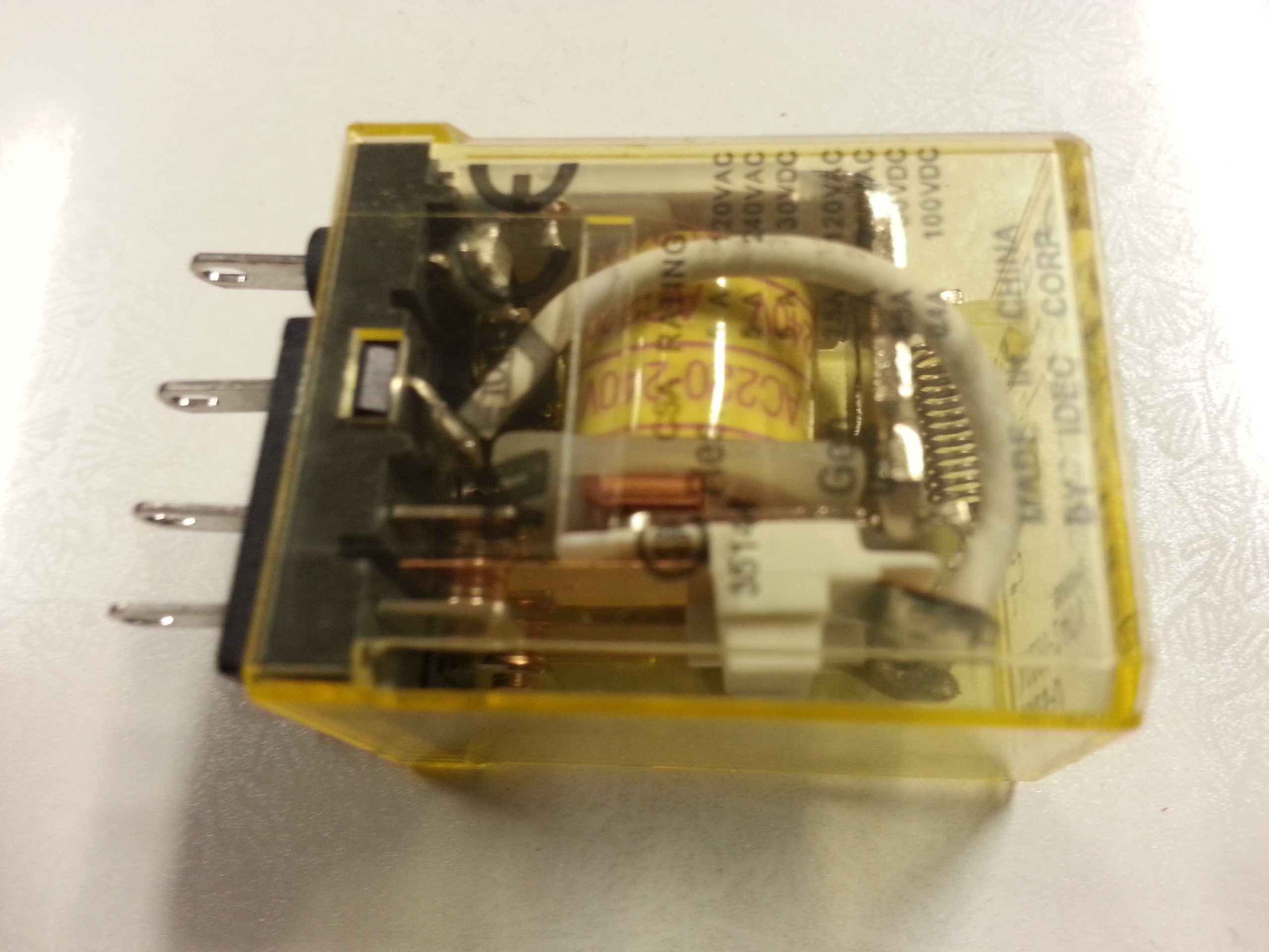
- Use a 220 V AC relay with 4 connection terminals :
- 2 terminals marked A1 and A2 for the AC 220 V coil;
- 2 terminals marked 1 and 2 for the contact.
- To operate this type of relay :
- Press and hold the push button, which allows the relay to stick, and by closing its contact, it will power your horn or siren.
- By releasing the push button, the circuit opens and drops the relay to cut your horn or siren.
Attach the relay
The modular type relay is easily and instantaneously fixed on a rail provided for this purpose in the electrical panels.
Important: before any intervention on the electrical network, make sure that your main circuit breaker is switched off and check for the absence of voltage with a multimeter.
- Identify in which panel you will mount your relay: either in your main panel located near your main circuit breaker or in a secondary panel.
- Once you have identified it, remove the protective cover by unscrewing its 4 fixing screws.
- Check the presence of voltage with your multimeter to work in complete safety.
Good to know: don’t neglect safety when working with electricity.
Locate a free space on the mounting rail.
- Position your relay on the top of the rail and clip down. A significant click will ensure that it is securely in place.
Connect the relay
Good to know: make sure to protect your relay with a circuit breaker calibrated to your receiver’s amperage.
- Make the connection according to the electrical diagram.
- 2 cables will arrive in your panel, one for the push button and the other for the siren.
- Strip the 2 cables to be able to connect the wires.
Good to know: 3G1.5 mm² cables (2 active wires + earth) generally have 3 colored wires, brown, blue, and green/yellow.
- Start by connecting the control circuit, which corresponds to the push-button cable.
- Strip the wires to the desired length:
- so that it can be fitted with a crimping tip in the case of a flexible wire ;
- so that the copper is not visible outside the terminal in the case of a rigid wire.
- First, connect the brown wire to the right-hand terminal under your circuit breaker.
Necessary: the right terminal is supposed to be the phase because the neutral must always be on the left.
- Then take the second wire of the push wire, the blue one, and connect it to your relay’s A1 terminal.
- Connect terminal A2 to terminal N (the neutral) under the circuit breaker.
- Then connect the power circuit.
- Strip your siren cable, which also has 3 wires, just like your push wire.
- Connect the brown wire to terminal 2 of your relay and the N terminal’s blue wire underneath the circuit breaker.
- Make the connection between the right-hand terminal located under your circuit breaker and terminal 1 of your relay.
- Connect the 2 green/yellow wires of the 2 cables to the grounding strip of your panel.
- Close your panel.
Test the connection
- Try out your circuit now.
- Turn your circuit breaker and main breaker ON.
- Press your push button. The siren should sound, or any newly connected components should operate.
If you are a good DIY enthusiast, the post from Part 1 and 2 should help you modify your car’s electrical system. Or, the next time your car electrician talks about connecting a car relay in your vehicle, you’ll know what it is for.